
Kemtron considers enclosure design and the important role it plays in creating an RFI seal to be compliant with EMC requirements of electrical and electronic equipment.
EMC shielding specialist, Kemtron explains the changing requirements on engineers for designing cabinet enclosures and the kind of shielding systems that can be deployed in different applications.
With increasingly complex RF environments in highly connected products that are required to meet the EMC directive, enclosure shielding is becoming even more important. This requirement is becoming more complex as frequencies in the new generation of equipment are increasing.
In the past, up to 18GHz was about the top end but 40GHz shielding is now required for many applications and with 5G, this can go even higher. Some RFI/EMI screening materials will not screen at these high frequencies so it is important to know the frequency requirement and environment of the enclosure before choosing shielding gaskets and components.
The use of shielding
RFI/EMI screening is a discipline that is of interest to both the electronic engineer and the enclosure design engineer. The electronic engineer must take EMC into account when designing PC boards by careful component and circuit layout, using PCB shielding cans as small Faraday cages over problem components, paying attention to wiring runs, use of filters and ferrites etc. This can eliminate the majority of EMI emissions. However, circuit design and layout may not be sufficient to attenuate emissions to the required levels and shielding of the enclosure may also be necessary.
This is where the enclosure design engineer is required to design the casing with sufficient thought to using EMI screening gaskets at joint interfaces. Although the brief may be to make the enclosure as small as possible, if this is not taken into consideration early on then this can result in an enclosure with no landed area on which to place an EMI screening gasket. This would require very expensive redesign or the use of more complex and expensive gasket materials and configurations.
Enclosures can be made of any material provided it is electrically conductive and will form a Faraday cage. Metallic enclosures have this characteristic, however all plastic enclosures need to be made conductive by applying a conductive coating to the inner surface. This can be done using conductive paints, electroplating or vacuum metallisation.
Screened enclosures are rarely a simple case of a closed box design and may have openings for optical displays, ventilation and cable entry. Examples of these areas that may have to be screened include:
* Optical displays with the use of a screened optical windows which can be made by using fine wire meshes laminated in glass or clear plastic such as acrylic or polycarbonate or conductive clear coatings on the substrate such as indium tin oxide.
* Enclosure ventilation can be screened using simple pierced or expanded metal in low performance applications or with the use of honeycomb ventilation panels made of aluminium or steel in higher performance applications.
* Cable entry into a screened enclosure needs to have the cable screening bonded to the conductive surface of the enclosure through a screened cable entry gland or screened connector.
Flange/gasket design and considerations
The design requirements for a gasket joint in a screened enclosure are primarily that there must be good electrical conductivity between opposing flanges through the gasket. Poor conductivity or high resistance between the flange and the gasket will result in poor shielding and if in areas there is no contact with the gasket this can result in a gap which could possibly act as a slot antenna making things worse, it is therefore important to consider fixing pitch and gasket compression forces to ensure a good continuous seal.
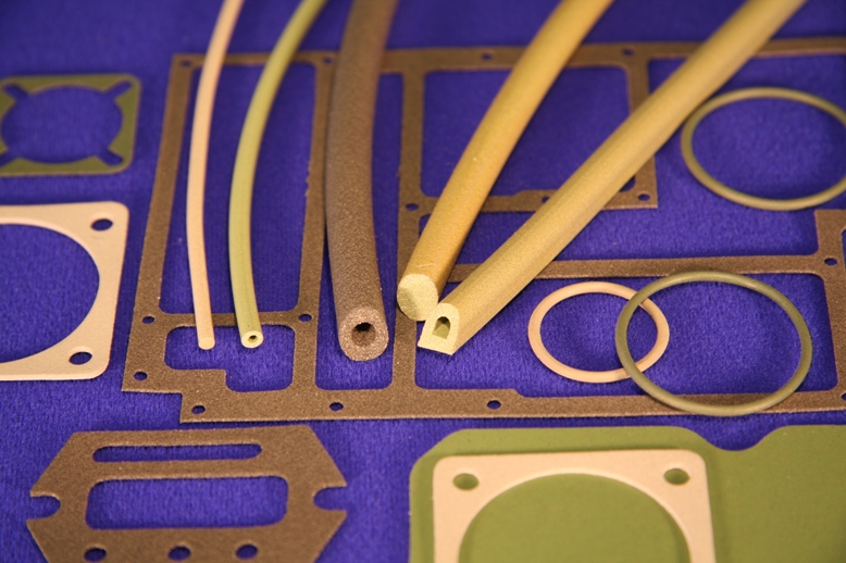
Surface mounted gaskets
Surface mounted gaskets such as electrically conductive elastomeric gaskets, knitted wire mesh conductive fabric over foam, beryllium copper finger strips etc, aim to compress the gasket between 10% and 50%, 10% being the minimum with a solid conductive elastomer style of gasket and up to 50% with hollow tubular or cellular styles.
Some form of compression stop or limit is essential with surface mounted gaskets to eliminate the possibility of over compression. These compression stops can be built into many styles of gaskets or made as an integral part of the flange and their height should be equal to that of the maximum compressed height of the gasket.
Conductive fabric over foam and beryllium copper fingers can be compressed further than mesh and elastomeric gaskets but lack the benefits of environmental sealing.
Very small land widths can be gasketed with a “form in place” conductive elastomer bead deposited directly to the gasket surface. This technology is particularly suited to gasketing complex multi compartment labyrinth machined enclosures. Bead sizes can be from 0.5mm wide, electrically conductive and non-conductive beads are available and can be placed in tandem to give EMI and environmental sealing.
Gaskets in grooves
For typical electronic enclosures, groove mounted gaskets such as “O” rings are generally a better option than surface mounted gaskets as when the gasket is compressed in the groove the two mating flanges can come into contact with each other thereby enhancing the screening performance by improving low contact resistance, “O” rings in grooves are also a much more cost effective solution and the groove also acts as a compression stop, thus protecting the gasket.
Most types of gaskets can be fitted into grooves, however a solid conductive elastomer gasket when compression forces are applied cannot change volume and has to deflect, and therefore the groove needs to be the same volume or more as the gasket to let the gasket material fill the space provided for it. If the gasket overfills the groove, damage and gasket failure can occur when the mating flanges are closed together.
Corrosion
An EMC gasket that is placed between two conductive surfaces is generally of a different material to the mating surfaces. In certain conditions this can lead to severe problems of bimetallic galvanic corrosion and degradation in shielding effectiveness. There are two ways of reducing the corrosion risk. One is to use a separate non-conductive environmental seal outboard of the EMC seal therefore isolating the joint from the environment. This would allow the use of materials that would otherwise be unsuitably matched. However, limitations on flange widths and the increased cost of using two gaskets can make this impractical.
A far better method is to try and match as near as possible the material of the gasket and the flanges thus reducing the electro potential difference between them.